Thursday, February 26, 2015

my journal log !!!

So my two lovely group partners created a DC circuit !!! 
As you can see, the battery is the source of energy that starts the circuit 
.Since the circuit only flows in one direction, the circuit is polarized. Now lets see my journal log on my lovely circuit


I divided my log into 3 sections , Input ,output, description.  The input is the slide dimmer ,the output is the component that acts as the capacitor. 


As i said before , I created an ac circuit, meaning that it flows in one direction. The slide dimmer acts an switch ,because it controls the amount of voltage in the circuit, The farther you push the switch the more sound it will produce. So the slide dimmer is considered an resistor. The output component acts as an capacitor ,because it stores the electricity in the circuit and releases it by sound  The sound coming out is the amount of voltage that has bypasses the resistor. 


Tuesday, February 24, 2015

My Dradio Teardown Documentation

So me and my amazing group teared down a Dradio together . My group consisted of Me, Romario, And a girl ,which i forgot her name 😣.  So now lets start with the the tools we used. ☺️

Tools 

- This tool is called a Desoldering gun. This tools will come in handy later on when you are desoldering a Dradio :)


- This tool is called a soldering iron. This tools is a big necessity when you are trying to remove the components in a Dradio ,as well as when you are desoldering. Warning !!!!, don't touch the top when it is turned on because it will burn you !!!!!!!😫


- Every time you use a soldering iron , you have to lightly brush the tip with  the spongy thingy. Remember , after every trial !!!! 👌


As you can see , the sponge is used a lot . Poor spongy 😔.Anyways lets go on.


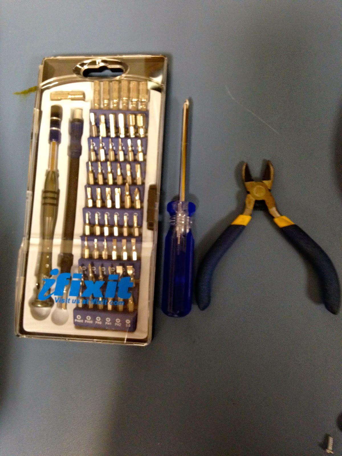
- although this tool is used to cut wires, this tool is extremely useful when trying to remove hard components in a mother board


Now lets begin the process, which is to start desoldering !!!!!!!!!

As you can see , you will have to lightly touch each joint with the the soldering iron until you see it melting . At the moment ,you will press the black button on the Desoldering gun to remove the joints. courtesy to my team mate Romario for showing us in the photos how its done 😁


Now that we have removed all the  joints ,we are going to remove the components


As you can see there are a lot of componenst ,so lets start labeling theses components to make it easy for you guys ☺️


Components 


- optocoupler : allows you to concoct two circuits that do not share a common power supply 


-Resistors: Resist the the flow of electrical energy in a circuit ,changing the voltage  and a current as a result


Capacitors: components that store and release electrical energy in a circuit


Tilt Sensor- a type of switch that will open or close depending on its orientation 


Piezo: An electrical current that can be used to detect vibrations and create noises


Jumper wire: wire used to connect components to each other on the mother board 


Now that we know the parts , let's remove these bad babies from the mother board 😜

In order to remove the components from the mother board , you have to lightly touch the joints connecting the components using  the soldering iron . With the help of another person , the assistant has to yank off the component lightly using the wire cutter when the joint is melting .


As you can see my wonderful partners are working together Ramario is nanking off the components ,while my other lovely partner is burning the connecting joints.
 Team work!!!!!! 😁


Before : 


phase 1 : With components


After: 
Phase 2- without components


 And i am done guys , click here for more cool stuff 😃😎
ps i am hungry 😣


Tuesday, February 10, 2015

My complete teardown blog documentation assignment


Breaking Apart a Fisher price baby toy     http://makercommons.org/assignment/ct-137-hacking-and-building-assignment-for-the-week-of-february-8/

I was given the task to disassemble any electronic object and i chose a fisher price baby toy. Disassembling a simple electronic object would give me a fresh start in learning what's necessary in the mechanical world. 

Despite the fact that a fisher price toy may seem simple, theres a lot of components needed in making the toy function. The use of micro controls has allowed the toy  to make sounds when switching the lever up and down.


Supplies needed in disassembling 


  • screwdriver
  • wire cutter 

Removing the screws placed on the back of the fisher price toy is the first step in opening up the toy. It was hard  removing  the screws ,but once doing so , I was keenly interested on the microprocessor connecting the halves with wires upon opening up the toy.


Disassembling the inside 


The next crucial step I took was removing the screws placed inside the halves and was amazed at what I was seeing. Upon removing the screws , i came across a lighting processor placed on the back side of the toy, which is responsible for the lighting in the toy.


`


Once I removed  the screws from the front halve , I was able able to spot a couple of stuff.  I noticed that there were two micro controller ships and a micro processor .


The last thing left was to cut off the wires from their connectors and that required the use of the wire cutter .I carefully cut the tips where the wires started.


Tuesday, February 3, 2015

I have always been keenly interested in building new things. I am very imaginative and I am always seeking for something out of the ordinary.  In my ct137 class, I expect myself to create something I wouldn't have thought I would never make . To be able to have so many ideas in your head and make it a reality is awesome. I am going to enjoy this class.